FAQ Regarding (EEC-IV), Incl 8v & 16v, Turbo & NA
FAQ Regarding (EEC-IV), Incl 8v & 16v, Turbo & NA
![]() by Captain Tightpants on Wed Dec 29, 2004 9:28 pm
by Captain Tightpants on Wed Dec 29, 2004 9:28 pm
So, thought I would compose a fairly comprehensive FAQ!
Firstly a brief description of how and why:
Introduced in 1990. The EEC-IV module is the heart of the electronic engine control system and is based on a microprocessor-controlled electronic circuit. It compares signals from its various electronic sensors with stored engine operating parameters, varying the engines operating settings directly according to engine load and environment.
Ignition is electronic via a DIS (Distributerless Ignition System) coil and E-DIS 4 module. From signals generated by the crankshaft position sensor (CPS), the E-DIS 4 module generates a profile ignition pulse (PIP). From this PIP, the EEC-IV module calculates a Spark Advance Word (SAW) as a means of defining ignition timing (or firing point). The E-DIS 4 module uses the SAW signal to control the DIS coil. If the EEC-IV module develops a fault, a Limited Operation Strategy (LOS) comes into effect allowing the driver to continue the journey but with restricted power and economy. Under LOS conditions SAW and PIP signals are not used.
The EEC-IV module is provided with a memory which is used for control matching, diagnosis and self testing.
With the engine running the E-DIS 4 module receives the SAW signal in a 'window' extending from 10 degrees ATDC to 170 degrees BTDC. The signal is therefore outside the ignition advance and retard range (10 degrees ATDC to 57 degrees BTDC) and cannot be influenced by HT disturbances.
When the engine is started or running at low speed, or operating in LOS mode, ignition is triggered by the E-DIS 4 module at 10 degrees BTDC and is not controlled by the SAW.
The DIS ignition coil consists of two coil windings converting the voltage signal from the E-DIS 4 module into HT and supplying this HT to the spark plugs in the correct firing order.
The crankshaft position sensor (CPS) is an inductive proximity switch reacting to the 36 webs cast onto the rear of the flywheel. One web is missing causing a gap and is used to denote 90 degrees BTDC on number one cylinder in the firing order. The signal generated by the CPS is used by the E-DIS 4 module to determine actual ignition timing. On engines with an open loop principle (as opposed to those with a closed loop incorporating a catalyst and HEGO sensor), the CO adjustment, a 5 kohm potentiometer supplies a substitute CO value to the EEC-IV module in place of the HEGO sensor. (Heated Exhaust Gas Oxygen Sensor).
Moving swiftly on, here is a wiring diagram of the FRST engine loom:

This covers the main parts of the EEC-IV, it does not include the EDIS-4, however that is fairly self explanitory.
A photograph of an OFAC engine loom:

Key:
1: ECU
2: MAP sensor
3: Diagnostics connector & CO Idle adjust connector
4: Current return
5: EDIS-4 connector
6: Crank Position Sensor
7: Connector to engine loom (injectors etc)
8: Speed Sensor
9: DIS Coil
10: Oil pressure switch
11: Amal Valve
12: Current return
13: Idle Speed Control Valve
14: CO Adjust POT
15: Connector to car loom
The connector to car loom is configured in the following way:
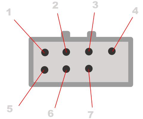
Looking onto the engine loom connector
Pin 1: Ignition Live
Pin 2: Pin 22 (ECU) to the Fuel Pump Relay
Pin 3: Fed From DIS coil pack to the Rev counter
Pin 4: Pin 20 (ECU) Current return
Pin 5: Pins 57 & 37 (ECU) to the Fuel injection Relay
Pin 6: Oil Pressure
Pin 7: B+ (Constant Live)
Pinouts & wiring colour information: OFAC,
1, Red -- +ve
3, Brown/Yellow – octane / idle adjust
4, Brown/White – speed sensor
7, Brown/Green – engine temperature sender
16, Brown – current return & 40
17, Brown/Green – diagnostics connector
20, Brown – current return
21, Brown/Yellow – idle speed valve
22, Brown – fuel pump relay
23, Brown/Red – octane / idle adjust
24, Brown/Blue – octane / idle adjust
25, Brown/Yellow – air temp sensor
26, Brown/Black – throttle sensor & co adjust pot & map sensor
27, Brown – CO adjust potentiometer
28, Blue/Yellow – Pin 2 on edis (disconnected)
33, Brown/Green – Boost control valve
36, Blue/Red – Pin 3 on edis
37, Black – idle speed valve & injectors & Speed sensor & Boost control (tbc) & 57
40, Brown – current return & 16
45, Brown/Yellow – map sensor
46, Brown – map sensor & engine temp & air temp & throttle & CO adjust
47, Brown/Green – throttle sensor
48, Blue/Green – diagnostic connector
56, Blue/Yellow – Pin 1 on edis
57, Black – idle speed valve & injectors & Speed sensor & Boost control (tbc) & 37
58, Brown – Injectors
59, Brown – Injectors
60, Brown – current return
Pinouts & wiring colour information: OFAB,
1, Red -- +ve
3, Brown/Yellow – octane / idle adjust
4, Brown/White – speed sensor
7, Brown/Green – engine temperature sender
8, Brown – CO adjust potentiometer
16, Brown – current return & 40
17, Brown/Green – diagnostics connector
20, Brown – current return
21, Brown/Yellow – idle speed valve
22, Brown – fuel pump relay
23, Brown/Red – octane / idle adjust
24, Brown/Blue – octane / idle adjust
25, Brown/Yellow – air temp sensor
26, Brown/Black – throttle sensor & co adjust pot & map sensor
27, Brown/Yellow – map sensor/via supressor
33, Brown/Green – Boost control valve
36, Blue/Red – Pin 3 on edis
37, Black – idle speed valve & injectors & Speed sensor & Boost control (tbc) & 57
40, Brown – current return & 16
46, Brown – map sensor & engine temp & air temp & throttle & CO adjust
47, Brown/Green – throttle sensor
48, Blue/Green – diagnostic connector
56, Blue/Yellow – Pin 1 on edis
57, Black – idle speed valve & injectors & Speed sensor & Boost control (tbc) & 37
58, Brown – Injectors
59, Brown – Injectors
60, Brown – current return
Firstly, anybody who has converted to OFAB, from OFAC, or N/A EEC-IV. This is important!! What has not been included in the above is the essential use of a MAP supressor! The supressor is a black box, about 30mm square and 8mm deep, it has three wires coming out of it, and is located on the bulkhead near the MAP sensor.
It is connected in the following way: (excuse the crumby diagrams!)

If you do not have this connected, you run the risk of damaging either/or the MAP sensor or ECU. It will also feed the ECU incorrect information, causing running problems, and/or damage to the engine. It may seem however that the engine is running with no problems.
A diagram of the MAP sensor and supressor plugs, looking on to them, at the engine loom.

It's worth noting, that these supressors are no longer available from Ford, and when they were available, they were £100 odd!
However, if you need one, speak to Kenny at Motorsport Developments,
Unit 3F, Moor Park Industrial Estate, Kincraig Road, Bispham, Blackpool, Lancashire, FY2 0HF, 01253 508400. He will supply you one new for £50, delivered.
Converting an 8v 2i loom to OFAC
1) EDIS Module pin 2 (blue/yellow) may now be disregarded as it is not used by the 0FAC/OFAB ECU's (pin 28 on ECU).
There are no MAP sensor pin changes as the OFAC MAP sensor is the same plug as the 2i MAP Sensor, so just plug and play.
Converting an OFAC loom to OFAB
1) At the ECU, pin no. 27 (marked on the multiplug, brown wire) needs moving to pin 8, which is empty (this is the CO adjuster signal wire).
2) Pin no. 45 (brown/yellow) needs moving to pin 27 - this is for the MAP sensor.
Some of the above information is saved from a very oily notepad, so there is likely to be some arse ups, if there are tell me and I will change them.
Hope they are of some help to a few peeps! (James!)
Steve

- Captain Tightpants
- Elite Post Master


- Posts: 3723
- Joined: Fri Feb 20, 2004 8:25 pm
- Location: Somerset

![]() by FezzR on Wed Dec 29, 2004 9:48 pm
by FezzR on Wed Dec 29, 2004 9:48 pm
you can add info that i found out about mapping EEC if you like but im too lazy to right long stuff like that at mo,
a good book on EEC-IV is
How to understand, service and modify
FORD FUEL INJECTION &
ELECTRONIC ENGINE CONTROL
By Charles O. Probst, SAE
starts right at the basic of how each sensor work, right through to sample layouts. only down side is all wiring diagrams are US vehicles

- FezzR
- God Damn Lazy
- Posts: 11755
- Joined: Sun Apr 21, 2002 7:27 pm
- Location: Wanaka, NZ
![]() by Captain Tightpants on Wed Dec 29, 2004 10:59 pm
by Captain Tightpants on Wed Dec 29, 2004 10:59 pm
http://www.vanaaken.com/europe/protuners/fordchiptuning.htm
http://www.tunercat.com/tnr_desc/links.html
http://www.systronix.com/home.htm
http://www.eec-tuner.com/
http://www.arlabs.com/index.htm#ABOUT%20THE%20EPROM+
http://www.pcmx.net/pcmx/
http://www.ckc.u-net.com/ecu/distributorless.htm
http://www.austincc.edu/cloud/tc_auto.html
Steve
- Captain Tightpants
- Elite Post Master
- Posts: 3723
- Joined: Fri Feb 20, 2004 8:25 pm
- Location: Somerset
![]() by FezzR on Wed Dec 29, 2004 11:10 pm
by FezzR on Wed Dec 29, 2004 11:10 pm
ive got some emails about the Race logic emulators that VanAken sell and i am perfectly willing to share this info, but im not going to post it on here untill i get the go ahed from them as they have the legal bowlorks on it,
i emailed them a few times cos there website isnt too clear
- FezzR
- God Damn Lazy
- Posts: 11755
- Joined: Sun Apr 21, 2002 7:27 pm
- Location: Wanaka, NZ

- Smo
- Elite Post Master

- Posts: 8658
- Joined: Sun Dec 29, 2002 12:33 am
- Location: My indecisive mind, in Thanet, Kent.
Car: 1990 Ford Fiesta Popular Plus
Re: FAQ Regarding FRST (EEC-IV) Wiring & Looms
![]() by heeman10 on Thu Dec 30, 2004 1:28 pm
by heeman10 on Thu Dec 30, 2004 1:28 pm
scort :Hope they are of some help to a few peeps! (James!)
Indeed they are

James .:. 193bhp/245lbft Zetec Turbo Mk3. Click sig for conversion thread + videos .:.
- heeman10
- Elite Post Master
- Posts: 28746
- Joined: Fri Nov 08, 2002 5:32 pm
- Location: Somerset
- Your car: Audi TT TDI Quattro S line
![]() by Robz_Fester on Thu Dec 30, 2004 1:58 pm
by Robz_Fester on Thu Dec 30, 2004 1:58 pm
I won't be using it in the near future but looks bloody handy
- Robz_Fester
- Elite Post Master
- Posts: 3608
- Joined: Thu Jan 01, 1970 1:00 am
- Location: Bournemouth
![]() by heeman10 on Fri Jan 14, 2005 12:00 am
by heeman10 on Fri Jan 14, 2005 12:00 am
James .:. 193bhp/245lbft Zetec Turbo Mk3. Click sig for conversion thread + videos .:.
- heeman10
- Elite Post Master
- Posts: 28746
- Joined: Fri Nov 08, 2002 5:32 pm
- Location: Somerset
- Your car: Audi TT TDI Quattro S line
![]() by heeman10 on Fri Jan 14, 2005 12:03 am
by heeman10 on Fri Jan 14, 2005 12:03 am
James .:. 193bhp/245lbft Zetec Turbo Mk3. Click sig for conversion thread + videos .:.
- heeman10
- Elite Post Master
- Posts: 28746
- Joined: Fri Nov 08, 2002 5:32 pm
- Location: Somerset
- Your car: Audi TT TDI Quattro S line
![]() by FezzR on Fri Jan 14, 2005 12:05 am
by FezzR on Fri Jan 14, 2005 12:05 am
heeman10 :I think the Burton Power Catalogue has some info in the back about EFI systems
i have a whole book on EEC-IV and its not in burton cat., and no im not gonna scan pages, and im busy reading other books to go back to that one and confuse myself,
Scort (smiler
- FezzR
- God Damn Lazy
- Posts: 11755
- Joined: Sun Apr 21, 2002 7:27 pm
- Location: Wanaka, NZ
![]() by Captain Tightpants on Fri Jan 14, 2005 12:12 am
by Captain Tightpants on Fri Jan 14, 2005 12:12 am
Heeman10 :Oi Steve have you been to http://www.antandpete.co.uk? You might enjoy the bike track day vids
The injectors have landed mate! They should be with us monday/tuesday next week. They were quick! Top find mate!
FezzR :Scort (smiler) - my thoughts exactly
LOL at the Burtons Degree!!
- Captain Tightpants
- Elite Post Master
- Posts: 3723
- Joined: Fri Feb 20, 2004 8:25 pm
- Location: Somerset
![]() by heeman10 on Fri Jan 14, 2005 12:15 am
by heeman10 on Fri Jan 14, 2005 12:15 am

Will PM my address through now, am hoping to go home next Friday night, so would be handy if they were there then so I can have a look. Very good find indeed
James .:. 193bhp/245lbft Zetec Turbo Mk3. Click sig for conversion thread + videos .:.
- heeman10
- Elite Post Master
- Posts: 28746
- Joined: Fri Nov 08, 2002 5:32 pm
- Location: Somerset
- Your car: Audi TT TDI Quattro S line
![]() by sailorbob on Tue May 03, 2005 10:00 am
by sailorbob on Tue May 03, 2005 10:00 am
FezzR :ive got some emails about the Race logic emulators that VanAken sell and i am perfectly willing to share this info, but im not going to post it on here untill i get the go ahed from them as they have the legal bowlorks on it
I'd be very interested in these if you are willing to e-mail them direct to me. Cheers.
- sailorbob
- Elite Post Master
- Posts: 1430
- Joined: Sun Aug 10, 2003 10:52 am
![]() by FezzR on Tue May 03, 2005 11:05 am
by FezzR on Tue May 03, 2005 11:05 am
basically is mega money and by there admission the software is crap, so thats more money, ill check tonight for you tho
- FezzR
- God Damn Lazy
- Posts: 11755
- Joined: Sun Apr 21, 2002 7:27 pm
- Location: Wanaka, NZ

![]() by Horace Peregrine on Tue May 03, 2005 10:26 pm
by Horace Peregrine on Tue May 03, 2005 10:26 pm
- Horace Peregrine
- Newbie Poster

- Posts: 3
- Joined: Tue May 03, 2005 10:00 pm
- Location: Chipping Campden
![]() by sailorbob on Wed May 04, 2005 11:01 am
by sailorbob on Wed May 04, 2005 11:01 am
Horace Peregrine :http://www.moates.net/
Mostly GM ALDL, but there are some EEC-IV parts on there too.
The Autoprom allows eec-iv and eec-v emulation through the J3 port with the J3 adapter cards.
Mark Mansur's TunerPro software is now eec code friendly and when he gets v4.1 out it should be even better.
- sailorbob
- Elite Post Master
- Posts: 1430
- Joined: Sun Aug 10, 2003 10:52 am
![]() by sailorbob on Thu May 05, 2005 11:33 am
by sailorbob on Thu May 05, 2005 11:33 am
I've corresponded with quite a few people in the states who have and I'm getting fairly close to doing an engine running emulation myself. I'll probably try out a 2.0l Mondeo first and tinker with stuff like idle speed and dealing with shutting EGR functions off etc before moving onto changing engine displacement, injector size, spark timing etc. If all goes to plan the idea is drop a bare bones (ie with all EGR, secondary air injection etc all stripped off) ported, cammed 2.0l into a Westfield. Following this a supercharged MR2 mk1 engine will follow.
- sailorbob
- Elite Post Master
- Posts: 1430
- Joined: Sun Aug 10, 2003 10:52 am
![]() by FezzR on Thu May 05, 2005 1:23 pm
by FezzR on Thu May 05, 2005 1:23 pm
sailorbob :Looks like we've hijacked this thread....
I've corresponded with quite a few people in the states who have and I'm getting fairly close to doing an engine running emulation myself. I'll probably try out a 2.0l Mondeo first and tinker with stuff like idle speed and dealing with shutting EGR functions off etc before moving onto changing engine displacement, injector size, spark timing etc. If all goes to plan the idea is drop a bare bones (ie with all EGR, secondary air injection etc all stripped off) ported, cammed 2.0l into a Westfield. Following this a supercharged MR2 mk1 engine will follow.
its all relavant eec-iv
how are you planning to get from an ecu dump hex code to a workable map tho, this is the only thing stopping me from going ahead at the moment due to the techniques and time required, there is plenty of people that can tell you all you need to know about 5.0l mustang ecus etc, but when it comes to any of the fiesta mondeo escort
and from what ive read the only "easy" way to do it is to use expensive software that can work out bits of it for you
- FezzR
- God Damn Lazy
- Posts: 11755
- Joined: Sun Apr 21, 2002 7:27 pm
- Location: Wanaka, NZ
![]() by sailorbob on Thu May 05, 2005 3:23 pm
by sailorbob on Thu May 05, 2005 3:23 pm
I use Computer Automotive Tuning System’s ‘Cross Disassembler’ (http://www.tunercat.com/) for my disassemblies though most people out there use Bill Lawrence’s disassembler (http://autos.groups.yahoo.com/group/EEC ... r%20tools/) which is free. I’ve not really tried out Bill Lawrence’s disassembler but it has the advantage of being able to set up a definition file to aid the disassembly process. I hear what you say about time, I’ve found it fairly laborious but I’m trying to understand how the code works too. A lot of code is common to all models and because of this in an early 90’s eec-iv I can find things like the MAF_TRANSFER_TABLE, SPARK_BASE_TABLE, SPARK_ALTITUDE_TABLE, SPARK_BORDERLINE_TABLE, IDLE_NEUTRAL_RPM, IDLE_DRIVE_RPM, INJECTOR_LOW_SLOPE, INJECTOR_HIGH_SLOPE and CID_ONE_CYLINDER within 10 minutes.FezzR :how are you planning to get from an ecu dump hex code to a workable map tho, this is the only thing stopping me from going ahead at the moment due to the techniques and time required
Fiesta/Escort/Mondeo wise I spent most of my time working on a COSY (Small turbo Escort cossie) ecu and have done a fair bit on a DEWY (2.0l Mondeo) ecu, a lot of the code is very similar. I’ve also looked (a little bit) at an EARS (2.0l automatic Mondeo) and found parts are very similar. Finally, I’ve had the briefest of looks at 2FCD and BLOB ecu’s which again have some of the code the same. Certainly expensive software isn’t required and once you get started some things fall into place quite quickly.FezzR : when it comes to any of the fiesta mondeo escort
and from what ive read the only "easy" way to do it is to use expensive software that can work out bits of it for you
- sailorbob
- Elite Post Master
- Posts: 1430
- Joined: Sun Aug 10, 2003 10:52 am
![]() by FezzR on Thu May 05, 2005 4:40 pm
by FezzR on Thu May 05, 2005 4:40 pm
the EECTuner Group was something i found yesterday via moates forum downloaded some bits and bobs to play with, and loaded tunerpro last night to play with the sample map (makes it stupidly easy once its all done for you)
hope this all works out

- FezzR
- God Damn Lazy
- Posts: 11755
- Joined: Sun Apr 21, 2002 7:27 pm
- Location: Wanaka, NZ
![]() by sailorbob on Fri May 06, 2005 10:52 am
by sailorbob on Fri May 06, 2005 10:52 am
- sailorbob
- Elite Post Master
- Posts: 1430
- Joined: Sun Aug 10, 2003 10:52 am
![]() by FezzR on Fri May 06, 2005 3:42 pm
by FezzR on Fri May 06, 2005 3:42 pm
no code out of the ecu yet, because i dont have the hardware to achive it, and if i were to buy it, it would just be easier to buy all the bits in one go
you know much about the Ostrich on moates.net? does it replace the Burn1?
- FezzR
- God Damn Lazy
- Posts: 11755
- Joined: Sun Apr 21, 2002 7:27 pm
- Location: Wanaka, NZ
![]() by sailorbob on Fri May 06, 2005 4:19 pm
by sailorbob on Fri May 06, 2005 4:19 pm
To add realtime emulation (to change the chip contents on the fly) you need the Ostrich.
The items complement each other but the Ostrich doesn't replace the Burn1. I bought my Autoprom before the Ostrich was released, and whilst it's biased for GM's, it combines the functions of the Burn1 and Ostrich. If you have another chip burner you can get away with not needing the Burn1. A definite must have is an emulator, having to burn a chip every time you want to make a change is impractical and you'll soon tire of it. There are other emulators out there (eg Romulator) but I have no experience of them.
PS I've PM'd you regarding getting the code out of the ecu.
- sailorbob
- Elite Post Master
- Posts: 1430
- Joined: Sun Aug 10, 2003 10:52 am
Twitter
The second 20th Anniversary article, a dive into the history of how the site came about is available here: https://t.co/kbCfZ4sf0R
17:44, 4th December 2021 Twitter Web App
To celebrate https://t.co/wXVkvJipaS being 20 years old this year, I've written a series of articles detailing the… https://t.co/B0vE0Y3KvP
17:42, 4th December 2021 Twitter Web App
Follow fiestaturbo.com on Twitter:
http://twitter.com/fiestaturbo/
Facebook
New article! fiestaturbo.com is 20 years old this year and I'm writing a series delving into the history of it. …
Saturday, 4th December 2021 12:49
Some awesome Escorts from the Fair - FORD FAIR 2021: ESCORT EXHIBITION - …
Sunday, 31st October 2021 17:05
All the best Focuses from Ford Fair - FORD FAIR 2021: FOCUS PEEKING - Which was your …
Thursday, 7th October 2021 22:21
Become a fan:
http://www.facebook.com/fiestaturbo/
RSS Feeds
Subscribe to the RSS feed
What is RSS?
RSS is a technology that lets you use special applications or modern browsers to notify you you when a site is updated. You can then read the updated content in that application or your browser.
To subscribe to these RSS feeds you need to copy the links above. For instructions on how to add it to the feeds you keep track of, consult the documentation of your RSS reader.